 |
| |
Low Speed Fixed Type AERATORS | 1 HP TO 100 HP | |||||||||||||||||||||||||||||||||||||||||||||||||||||||||||||||
| |
Low Speed Floating Cone Type AERATORS | 1 HP TO 100 HP | |||||||||||||||||||||||||||||||||||||||||||||||||||||||||||||||
| |
High Speed FRP Foam filled FLOATING AERATORS | 1 HP TO 50 HP | |||||||||||||||||||||||||||||||||||||||||||||||||||||||||||||||
| |
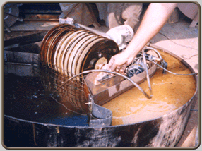
Cage ROTORS | ||||||||||||||||||||||||||||||||||||||||||||||||||||||||||||||||
| |
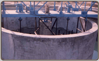
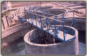
Central Driven CLARIFIERS | 4 MT. DIA TO 50 MT. DIA | |||||||||||||||||||||||||||||||||||||||||||||||||||||||||||||||
| |
Peripherally Driven CLARIFIERS | 4 MT. DIA TO 50 MT. DIA | |||||||||||||||||||||||||||||||||||||||||||||||||||||||||||||||
| |
TUBE AND PARALLEL SETTLERS | ||||||||||||||||||||||||||||||||||||||||||||||||||||||||||||||||
| |
THICKENERS | 4 MT. DIA TO 35 MT. DIA | |||||||||||||||||||||||||||||||||||||||||||||||||||||||||||||||
| |
Central Driven CLARIFLOCCULATORS | 3 MT. DIA TO 50 MT. DIA | |||||||||||||||||||||||||||||||||||||||||||||||||||||||||||||||
| |
Peripherally Driven CLARIFLOCCULATORS | 3 MT. DIA TO 50 MT. DIA | |||||||||||||||||||||||||||||||||||||||||||||||||||||||||||||||
| |
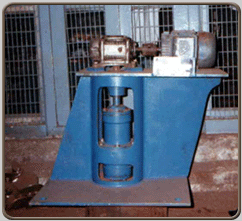
Low Speed AGITATORS | 0.5 HP TO 50 HP | |||||||||||||||||||||||||||||||||||||||||||||||||||||||||||||||
| |
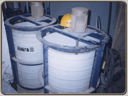
High Speed AGITATORS | 0.5 HP TO 50 HP | |||||||||||||||||||||||||||||||||||||||||||||||||||||||||||||||
| |
Manual and Automatic SCREENS | ||||||||||||||||||||||||||||||||||||||||||||||||||||||||||||||||
| |
GRIT PLANTS | ||||||||||||||||||||||||||||||||||||||||||||||||||||||||||||||||
| |
DIGESTER MIXERS | ||||||||||||||||||||||||||||||||||||||||||||||||||||||||||||||||
| |
OIL SKIMMERS | ||||||||||||||||||||||||||||||||||||||||||||||||||||||||||||||||
| |
CATALYTIC REACTORS | ||||||||||||||||||||||||||||||||||||||||||||||||||||||||||||||||
| |
Package SEWAGE Plants | ||||||||||||||||||||||||||||||||||||||||||||||||||||||||||||||||
| |
Flocculator | ||||||||||||||||||||||||||||||||||||||||||||||||||||||||||||||||
| |
Pressure Sand Filter (PSF) | ||||||||||||||||||||||||||||||||||||||||||||||||||||||||||||||||
| |
Activated Carbon Filter (ACF) | |
Trickling Filter/Rotary Distributor | ||||||||||||||||||||||||||||||||||||||||||||||||||||||||||||||
| |
CONSTANT HEAD TANK / CHEMICAL DOSER | ||||||||||||||||||||||||||||||||||||||||||||||||||||||||||||||||
| |
MESH TYPE AUTOMATIC SCREEN | AS FINE AS 2MM THICKNESS ** | |||||||||||||||||||||||||||||||||||||||||||||||||||||||||||||||
| TOP | |||||||||||||||||||||||||||||||||||||||||||||||||||||||||||||||||
|
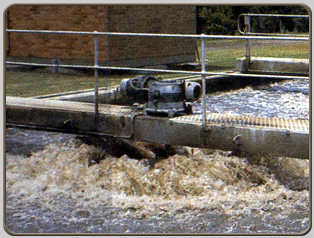
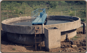
LOW SPEED FIXED TYPE AERATORS 1 HP TO 100 HP This unit is suitable for installation
in client’s concrete tank. Each unit will be mounted on concrete
supports and shall consist of :-
Oxygen transfer capacity shall be 2.2/Kgs./hr/ HP under standard testing conditions viz., 20° C, tap water, zero dissolved Oxygen. COMPARISON OF AERATOR TYPES
|
|||||||||||||||||||||||||||||||||||||||||||||||||||||||||||||||||
|
|
|||||||||||||||||||||||||||||||||||||||||||||||||||||||||||||||||
| TOP | |||||||||||||||||||||||||||||||||||||||||||||||||||||||||||||||||
|
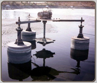
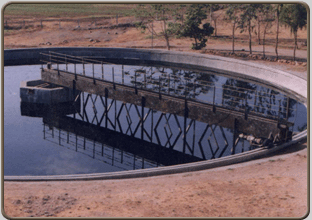
LOW SPEED FLOATING TYPE AERATORS 1 HP TO 100 HP |
|||||||||||||||||||||||||||||||||||||||||||||||||||||||||||||||||
| This
type of aerator is ideally suitable for installation in client’s
concrete tank or lagoons. Each unit will consist of :- - TEFC squirrel cage induction motor with IP55 degree of protection suitable for continuous outdoor operation. - Worm gear box.
SALIENT FEATURES OF KUNAL LOW SPEED FLOATING AERATOR Solid non-clog cone type Impeller giving maximum splashing, aeration and pumping. Floats are filled with high-density closed cell polyurethane foam making them life long with high safety factor for flotation. Floats are adequately sized to support the platform. |
|||||||||||||||||||||||||||||||||||||||||||||||||||||||||||||||||
|
|
|||||||||||||||||||||||||||||||||||||||||||||||||||||||||||||||||
| TOP | |||||||||||||||||||||||||||||||||||||||||||||||||||||||||||||||||
|
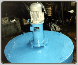
HIGH SPEED FLOATING AERATORS 1 HP TO 50 HP |
|||||||||||||||||||||||||||||||||||||||||||||||||||||||||||||||||
|
This unit is suitable for installation in client’s concrete
tank. Each unit will consist of :-
An External Bearing Housing is provided between motor shaft and aerator shaft, thus, protecting the motor from all types of loads and avoiding damage to any part due to misalignment. Thus, the unit becomes maintenance free. This feature also enables motor to be taken out without disturbing other parts. Float is of fiberglass structurally reinforced from within and filled with high-density closed cell polyurethane foam making it life long with high safety factor for flotation. Even people can sit on the float without any fear of the unit going up and down. The Impeller is in Stainless Steel (SS). It is Dynamically balanced, anti-fouling, non-cavitating, non clog Stainless Steel Propeller capable of achieving maximum aeration pumping and mixing. The Impeller pitch is designed for maximum hydraulic delivery without overloading the motor. Core (Intake chamber) is designed to retain more velocity energy in the fluid. This design feature also enables liquid to be drawn through the core at high velocity. Shaft is solid S. S. 304. COMPARISON OF HIGH SPEED AERATOR TYPES
|
|||||||||||||||||||||||||||||||||||||||||||||||||||||||||||||||||
|
|
|||||||||||||||||||||||||||||||||||||||||||||||||||||||||||||||||
| TOP | |||||||||||||||||||||||||||||||||||||||||||||||||||||||||||||||||
|
CAGE ROTORS |
|||||||||||||||||||||||||||||||||||||||||||||||||||||||||||||||||
|
|||||||||||||||||||||||||||||||||||||||||||||||||||||||||||||||||
|
|
|||||||||||||||||||||||||||||||||||||||||||||||||||||||||||||||||
| TOP | |||||||||||||||||||||||||||||||||||||||||||||||||||||||||||||||||
|
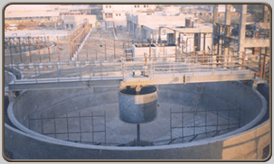
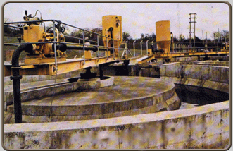
CENTRALLY DRIVEN CLARIFIERS 4 MT. DIA TO 50 MT. DIA |
|||||||||||||||||||||||||||||||||||||||||||||||||||||||||||||||||
This
unit is suitable for installation in client’s concrete tank. Each
unit will consist of :-
COMPARISON OF CLARIFIER
IN CLARIFIER FOLLOWING ITEMS ARE OPTIONAL :- - V-notch weir plate. - Skimmer blade. - Scum baffle. - Scum box. - Telescopic arrangement (excluding piping and valves in an around sludge pit).
|
|||||||||||||||||||||||||||||||||||||||||||||||||||||||||||||||||
|
|
|||||||||||||||||||||||||||||||||||||||||||||||||||||||||||||||||
| TOP | |||||||||||||||||||||||||||||||||||||||||||||||||||||||||||||||||
|
PERIPHERALLY DRIVEN CLARIFIERS 4 MT. DIA TO 50 MT. DIA |
|||||||||||||||||||||||||||||||||||||||||||||||||||||||||||||||||
|
|||||||||||||||||||||||||||||||||||||||||||||||||||||||||||||||||
|
|
|||||||||||||||||||||||||||||||||||||||||||||||||||||||||||||||||
| TOP | |||||||||||||||||||||||||||||||||||||||||||||||||||||||||||||||||
|
TUBE SETTLER (RCC TANK) |
|||||||||||||||||||||||||||||||||||||||||||||||||||||||||||||||||
| This
is a PLANT consisting of FLASH MIXER/FLOCCULATOR/SETTLING TANK.
FLASH MIXING tank with Flash Mixer. Each unit will consist of :- - TEFC squirrel cage induction IP55 motor. - Worm gear box. - Turbine type impeller. - Shaft. - Rigid coupling connecting gear box to agitator shaft. - Base plate with coupling. Support channels or beams across the tank shall be supplied and laid by client.
- Central shaft. |
|||||||||||||||||||||||||||||||||||||||||||||||||||||||||||||||||
|
|
|||||||||||||||||||||||||||||||||||||||||||||||||||||||||||||||||
| TOP | |||||||||||||||||||||||||||||||||||||||||||||||||||||||||||||||||
|
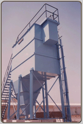
TUBE SETTLER (PREFABRICATED STEEL TANK) |
|||||||||||||||||||||||||||||||||||||||||||||||||||||||||||||||||
| This
is a COMBINED UNIT consisting of FLASH MIXER/FLOCCULATOR/SETTLING
TANK. FLASH MIXER tank. The tank will be fitted with a mechanism consisting of :-
SETTLING tank in steel (TUBE SETTLER). The unit shall be made of MS plates and the shell will have suitable supports with inlet, outlet and drain arrangement. It will have steel launder and collection pipes. Settling will be efficiently achieved by tubes which shall be special PVC units with high settling efficiency. The tubes shall be installed and fitted to make continuous settling area and shall be supported on steel supports. A common walkway with handrails shall be provided to cover Tube Settler and Flocculator/Flash Mixer. The tank shall be painted with Epoxy Primer and Epoxy Paint from inside and Red oxide Primer and Synthetic Enamel Paint from outside |
|||||||||||||||||||||||||||||||||||||||||||||||||||||||||||||||||
|
|
|||||||||||||||||||||||||||||||||||||||||||||||||||||||||||||||||
| TOP | |||||||||||||||||||||||||||||||||||||||||||||||||||||||||||||||||
|
SET TUBE SETTLER (PREFABRICATED STEEL TANK) |
|||||||||||||||||||||||||||||||||||||||||||||||||||||||||||||||||
|
SETTLING TANK :- The shell be made of MS plates and the shell
will have suitable supports with inlet, outlet and drain arrangement.
It will have steel launder and collection pipes. Settling will
the efficiently achieved by tubes which shall be special PVC
units with high settling efficiency. The Tubes shall be installed
and fitted to make continuous settling area and shall be supported
on steel supports. |
|||||||||||||||||||||||||||||||||||||||||||||||||||||||||||||||||
|
|
|||||||||||||||||||||||||||||||||||||||||||||||||||||||||||||||||
| TOP | |||||||||||||||||||||||||||||||||||||||||||||||||||||||||||||||||
|
PARALLEL PLATE (INCLINED PLATE SEPARATOR (IPSL) |
|||||||||||||||||||||||||||||||||||||||||||||||||||||||||||||||||
| Each
unit will consist of :- - Main shell of M. S. inside of tank. - Feed box. - Adjustable weir. - Inner support plate. - Necessary stiffeners. - Necessary leg supports in steel. - FRP plates. - Inlet/Outlet/Sludge/drain flanged connections. - The unit shall be painted with Epoxy paint from inside, and synthetic enamel paint from outside. |
|||||||||||||||||||||||||||||||||||||||||||||||||||||||||||||||||
|
|
|||||||||||||||||||||||||||||||||||||||||||||||||||||||||||||||||
| TOP | |||||||||||||||||||||||||||||||||||||||||||||||||||||||||||||||||
|
THICKENER MECHANISM 4 MT. DIA TO 35 MT. DIA |
|||||||||||||||||||||||||||||||||||||||||||||||||||||||||||||||||
|
|||||||||||||||||||||||||||||||||||||||||||||||||||||||||||||||||
|
|
|||||||||||||||||||||||||||||||||||||||||||||||||||||||||||||||||
| TOP | |||||||||||||||||||||||||||||||||||||||||||||||||||||||||||||||||
|
CENTRAL DRIVE CLARIFLOCCULATORS 3 MT. DIA TO 50 MT. DIA |
|||||||||||||||||||||||||||||||||||||||||||||||||||||||||||||||||
| This
unit is suitable for installation in client’s concrete tank. Each
unit will consist of :- - Fixed full bridge with walkway and handrail from one end to center.
All pipes including inlet, outlet and sludge pipes are excluded from our scope. SALIENT FEATURES OF “KUNAL” CENTRAL DRIVE CLARIFLOCCULATOR Unlike other Clariflocculators, having two separate drives, we offer a central paddle flocculator, which has flocculating paddles Intermeshing with vertical paddles attached with the scrapper arm. This provides a high degree of flocculation and hence is more efficient. |
|||||||||||||||||||||||||||||||||||||||||||||||||||||||||||||||||
|
|
|||||||||||||||||||||||||||||||||||||||||||||||||||||||||||||||||
| TOP | |||||||||||||||||||||||||||||||||||||||||||||||||||||||||||||||||
|
PERIPHERALLY DRIVEN CLARIFLOCCULATORS 3 MT. DIA TO 50 MT. DIA |
|||||||||||||||||||||||||||||||||||||||||||||||||||||||||||||||||
|
This unit is suitable for installation in client’s concrete tank. Each unit will consist of :-
|
|||||||||||||||||||||||||||||||||||||||||||||||||||||||||||||||||
|
|
|||||||||||||||||||||||||||||||||||||||||||||||||||||||||||||||||
| TOP | |||||||||||||||||||||||||||||||||||||||||||||||||||||||||||||||||
|
LOW SPEED AGITATORS 0.5 HP TO 50 HP |
|||||||||||||||||||||||||||||||||||||||||||||||||||||||||||||||||
This
is suitable for installation in client’s concrete tank. Each unit
will consist of :-
Support channels or beams across the tank shall be supplied and laid by client. SALIENT FEATURES OF “KUNAL” LOW SPEED AGITATOR - Sturdy Drive arrangement with a heavy base plate. - A heavy duty bearing housing to take care of axial/radial loads, bending moments and thrust loads. - Solid shaft adequately designed to resist bending moment. - Impeller designed for maximum turbulence and efficiency. |
|||||||||||||||||||||||||||||||||||||||||||||||||||||||||||||||||
|
|
|||||||||||||||||||||||||||||||||||||||||||||||||||||||||||||||||
| TOP | |||||||||||||||||||||||||||||||||||||||||||||||||||||||||||||||||
|
HIGH SPEED AGITATORS 0.5 HP TO 50 HP |
|||||||||||||||||||||||||||||||||||||||||||||||||||||||||||||||||
This
unit is suitable for installation in client’s concrete tank. Each
unit will consist of :-
|
|||||||||||||||||||||||||||||||||||||||||||||||||||||||||||||||||
|
|
|||||||||||||||||||||||||||||||||||||||||||||||||||||||||||||||||
| TOP | |||||||||||||||||||||||||||||||||||||||||||||||||||||||||||||||||
|
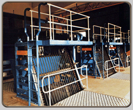
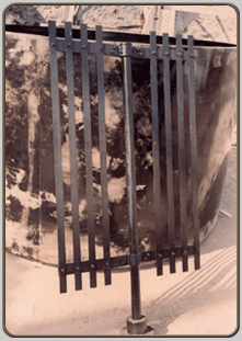
MANUAL BAR SCREEN |
|||||||||||||||||||||||||||||||||||||||||||||||||||||||||||||||||
This structure is suitable for installation in client’s concrete
screen chamber. Each unit will consist of :-
|
|||||||||||||||||||||||||||||||||||||||||||||||||||||||||||||||||
|
|
|||||||||||||||||||||||||||||||||||||||||||||||||||||||||||||||||
| TOP | |||||||||||||||||||||||||||||||||||||||||||||||||||||||||||||||||
|
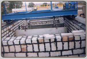
GRIT REMOVAL MECHANISM |
|||||||||||||||||||||||||||||||||||||||||||||||||||||||||||||||||
This
unit is suitable of installation in clients concrete tank. Each
unit will consist of :-
- Tie rods. |
|||||||||||||||||||||||||||||||||||||||||||||||||||||||||||||||||
|
|
|||||||||||||||||||||||||||||||||||||||||||||||||||||||||||||||||
| TOP | |||||||||||||||||||||||||||||||||||||||||||||||||||||||||||||||||
|
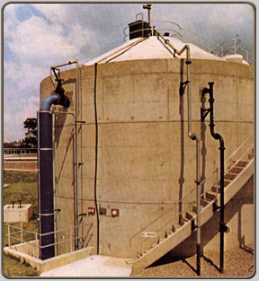
DIGESTER |
|||||||||||||||||||||||||||||||||||||||||||||||||||||||||||||||||
Each
unit will consist of :-
ACCESSORIES :- 1. Flame arrestor per digester. 2. Pressure Relief valves. 3. Vacuum Release valves. |
|||||||||||||||||||||||||||||||||||||||||||||||||||||||||||||||||
|
|
|||||||||||||||||||||||||||||||||||||||||||||||||||||||||||||||||
| TOP | |||||||||||||||||||||||||||||||||||||||||||||||||||||||||||||||||
|
MANUAL OIL SKIMMER |
|||||||||||||||||||||||||||||||||||||||||||||||||||||||||||||||||
This
is suitable for installation in client’s concrete tank. Each unit
will consist of :-
AUTOMATIC OIL SEPARATOR suitable for client’s Existing vessel. The unit will consist of :-
|
|||||||||||||||||||||||||||||||||||||||||||||||||||||||||||||||||
|
|
|||||||||||||||||||||||||||||||||||||||||||||||||||||||||||||||||
| TOP | |||||||||||||||||||||||||||||||||||||||||||||||||||||||||||||||||
|
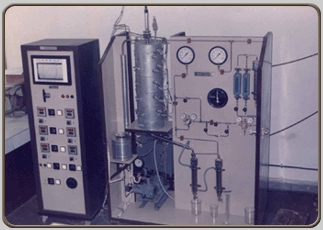
VAPOUR PHASE CATALYST TESTING UNIT/ REACTOR FOR CATALYST ACTIVITY MEASUREMENT. SIMILAR TO GEO MECHANIQUE OF FRANCE
|
|||||||||||||||||||||||||||||||||||||||||||||||||||||||||||||||||
|
I. The unit is an Asset for R & D. We have successfully supplied these units to Godrej Soaps Vikhroli, Mumbai, Herdilia Chemicals, New Bombay, Defence Research Institute, Gwalior. They have extensively used our units to collect useful data from which full-scale commercial plants have been scaled-up. Godrej Soaps Vikhroli, Mumbai :- They worked on our Laboratory unit for more than 1 year for Dehydration of Fatty Alcohols to Alpha - Olefins. Officers of CSIR, DGTD had visited and they were appreciative of the unit. Subsequently we built a Pilot Plant for Godrej soaps from which they collected data on the basis of which full scale plant of Gujarat Godrej Innovative Chemicals at Bharuch was constructed. Herdilia Chemicals, New Bombay :-They utilised the unit for their commercial project of Diphenyl Oxide (DPO). Defence Research Institute, Gwalior : For conversion of Amides
to Nitriles.
- Selectivity, Thermal stability and life of the catalysts. - Study of kinetics of chemical reactions. - Effect of various operating parameters such as temperature, flow rate, pressure etc. - Studies on poisoning and regeneration of catalysts. - Equilibrium Adsorption studies. III. The Set consists of two parts :- (1) Main equipment supported on a structure. (2) Instrumentation Panel. 1. The main equipment includes the following :- - Reservoir for liquid raw material. - Metering Pump. - Catalytic reactor. - Electrical heaters. - Product cooler. - Product receiver. - Inlet/outlet Gas Flow Meter (Cumulative and Flow). 2. The Instrumentation Panel include the following :- - Indicating temperature controllers. - Temperature Recorder (optional from 6 to 12 point or a scanner). - Electrical switches of all the equipment. IV. SPECIFICATIONS OF THE UNIT : Specifications of Catalyst Activity Measurement unit are given below :- - Maximum Operating Temperature : 550" c. - Maximum Operating Pressure : 20 Kg./cm2 (Higher pressures can be designed as per customers requirements). - Reactor capacity : Model - 1 : 250 cm3 Model - 2 : 400 cm3 - Maximum flow rate of liquid Model - 1 : 0.8 litres / hour. Model - 2 : 1.6 litres / hour. - Maximum gas flow rate : Model - 1 : 300 litres / hours. Model - 2 : 1000 litres / hour. - Temperature control accuracy : 1% of full scale. - Material of construction : SS 316 (all contact parts) - Power requirement : Model - 1 : Single phase, 4 kW. Model
- 2 : 3 phase, 6 kW. |
|||||||||||||||||||||||||||||||||||||||||||||||||||||||||||||||||
|
|
|||||||||||||||||||||||||||||||||||||||||||||||||||||||||||||||||
| TOP | |||||||||||||||||||||||||||||||||||||||||||||||||||||||||||||||||
|
PACKAGE SEWAGE PLANTS |
|||||||||||||||||||||||||||||||||||||||||||||||||||||||||||||||||
|
DESCRIPTION :- Package Plant is an ideal application for Hotels, Schools, Community, Hospitals, towns, villages, housing estates, and similar application, where space is limited and civil construction is not easy.
SALIENT FEATURES OF “KUNAL” PACKAGE PLANT :- Designs are based on World famous Simon Hartley of UK, who are pioneers in this field, since, 1902. Their SIMCAR Aerator gained world wide popularity. The systems involve judicial design, taking care of not only proper Aeration, but also mixing and pumping action in the Aeration Tank. KUNAL non clog Aerator ensures just that. Even the settling compartment is scientifically
designed to take care of entry velocities, short circuiting
and turbulence. Over flow weirs adequately designed to ensure
good settling resulting in a better over flow clarity |
|||||||||||||||||||||||||||||||||||||||||||||||||||||||||||||||||
|
|
|||||||||||||||||||||||||||||||||||||||||||||||||||||||||||||||||
| TOP | |||||||||||||||||||||||||||||||||||||||||||||||||||||||||||||||||
|
FLOCCULATOR |
|||||||||||||||||||||||||||||||||||||||||||||||||||||||||||||||||
|
|||||||||||||||||||||||||||||||||||||||||||||||||||||||||||||||||
| TOP | |||||||||||||||||||||||||||||||||||||||||||||||||||||||||||||||||
|
PRESSURE SAND FILTER
(PSF)
|
|||||||||||||||||||||||||||||||||||||||||||||||||||||||||||||||||
|
This is a unit used to remove balance of suspended solids carried over from Secondary Clarifier of a biological process or from Clariflocculator of a Water Treatment Plant. Thus, this is a Polishing unit used to make the water reusable, since, the suspended solids are less than 5 - 10 ppm. It is a MS fabricated/FRP vessel with dish ends, duly painted with anticorrosive paint. The vessel is packed with a bed of graded sand and gravels (media) on to which water is distributed from the top and then it percolates down-wards. The suspended solids get trapped in the media and clear water gets collected in the PVC laterals placed at bottom, from where it is taken out by gravity. Over a period of time, the media tends to get choked, at which time, the bed needs to be back-washed with clear water in an "Up-flow" manner. Piping with valves is provided for these operations. A set of pumps is required to pump the liquid at inlet, since there is a pressure drop across the bed. The same set of pumps can be used for back-washing also. FOR LARGER UNITS FOLLOWING ARE THE SPECIFICATIONS :- 1. PRESSURE SAND FILTER :- The unit will consist of :- - Cylindrical Pressure Vessel with Shell and Dish end. - Inlet distributor in M. S - Under drain system in M. S. - Air release line. - Frontal piping with following Cast Iron Double Flanged diaphragm valves :- - Inlet Valve. - Outlet Valve. - Upwash Valve. - Washout Valve. - Drain Valve. - Air release valve - 1 Man hole cover & 1 hand hole cover with lifting arrangement. - Sampling Arrangement : a) Raw Water with pressure gauge. b) Filtered Water with pressure gauge. - Sand Filter Media. FOR SMALLER UNITS FOLLOWING ARE THE SPECIFICATIONS :- 1. PRESSURE SAND FILTER :- The unit will consist of : - Cylindrical Pressure Vessel with valves and frontal piping and internals and filled with sand. |
|||||||||||||||||||||||||||||||||||||||||||||||||||||||||||||||||
|
|
|||||||||||||||||||||||||||||||||||||||||||||||||||||||||||||||||
| TOP | |||||||||||||||||||||||||||||||||||||||||||||||||||||||||||||||||
|
ACTIVATED CARBON FILTER
|
|||||||||||||||||||||||||||||||||||||||||||||||||||||||||||||||||
|
This is a unit generally, installed after Pressure Filter and is used to remove colour, sometimes BOD, smell and other obnoxious matter. It is a polishing unit used in Tertiary Treatment of Effluent/Sewage Treatment Plants, so that the water can be re-used/re-cycled. It is a MS fabricated/FRP vessel with dish ends, duly painted with anticorrosive paint. The vessel is packed with a bed of Activated Carbon supported on graded sand and gravels (media) on to which water is distributed from the top and then it travels down-wards. The suspended solids get trapped in the media and clear water gets collected in the PVC laterals placed at bottom, from where it is taken out by gravity. Over a period of time, the media tends to get choked. At which time, the bed needs to be back-washed with clear water in an "Up-flow" manner. Piping with valves is provided for these operations. A set of pumps is required to pump the liquid at inlet, since there is a pressure drop across the bed. The same set of pumps can be used for back-washing also. |
|||||||||||||||||||||||||||||||||||||||||||||||||||||||||||||||||
|
ACTIVATED CARBON FILTER :- The unit will consist of :- - Pressure Vessel with internal fittings. - Frontal pipe works. - Control Valves. - Initial charge of activated carbon. |
|||||||||||||||||||||||||||||||||||||||||||||||||||||||||||||||||
|
|
|||||||||||||||||||||||||||||||||||||||||||||||||||||||||||||||||
| TOP | |||||||||||||||||||||||||||||||||||||||||||||||||||||||||||||||||
|
TRICKLING FILTER/ROTARY
DISTRIBUTOR
|
|||||||||||||||||||||||||||||||||||||||||||||||||||||||||||||||||
|
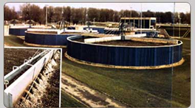
This is an alternate to activated sludge process. The Filter consists of bed of gravel/plastic media, etc. through which effluent/sewage is made to percolate. The filter serves both to oxidize and also bioflocculate the organic matter thereby reducing the BOD. The organic material is absorbed on the media for bacteria to degrade the same. The mechanism helps in uniformly distributing the water on the bed, at minimum head loss.
|
 |
||||||||||||||||||||||||||||||||||||||||||||||||||||||||||||||||
|
The mechanism is generally self propelled. |
|||||||||||||||||||||||||||||||||||||||||||||||||||||||||||||||||
|
TRICKLING FILTER MECHANISM suitable for installation in client's concrete tank. The unit will consist of :- - Arms. - Center column. - Top bearing assembly (turn table). - Nozzles. - Ropes. - Bottom base. - Cross head. - Hardware. |
|||||||||||||||||||||||||||||||||||||||||||||||||||||||||||||||||
|
|
|||||||||||||||||||||||||||||||||||||||||||||||||||||||||||||||||
| TOP | |||||||||||||||||||||||||||||||||||||||||||||||||||||||||||||||||
|
CONSTANT HEAD TANK/CHEMICAL DOSER This unit consists of:
|
|||||||||||||||||||||||||||||||||||||||||||||||||||||||||||||||||
|
- Constant head in M. S. / FRP / PP constructions. - Float. -Weir. -Handle. |
|||||||||||||||||||||||||||||||||||||||||||||||||||||||||||||||||
|
|
|||||||||||||||||||||||||||||||||||||||||||||||||||||||||||||||||
|
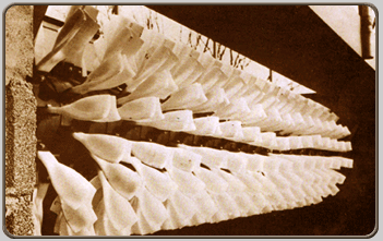
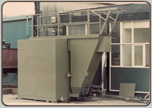
MESH TYPE AUTOMATIC SCREEN |
|||||||||||||||||||||||||||||||||||||||||||||||||||||||||||||||||
|
Background: The customer for one of their CETP project was looking for Automatic Screen with very fine openings. Screens commonly available in the market cannot function, since the devise engaging the screen bars will not function due to fine gaps. KUNAL ENVIRO ENGINEERS took this up as a challenge, applied themselves and came out with THIS UNIQUE SCREEN DESIGN NOT ENVISAGED SO FAR. WORKING/DESCRIPTION :- The Screen is made with a 2 mm opening Mesh. The Mesh rotates like a belt conveyor on rollers, but at an inclination. Rubber flaps at the upstream to guide flow are provided. When the mesh comes on the top side, the screenings fall on its own by gravity, and also additional scrapper is provided to facilitate removal. A platform is provided where the screenings can fall and water can be drained through perforated holes. Since the mesh , after one cycle , comes again in water, it becomes automatic self cleaning.
|
|||||||||||||||||||||||||||||||||||||||||||||||||||||||||||||||||
